Flaring is a combustion control process of volatile organic compound (VOC) in which the VOCs are piped to a remote location and burned in an open flame in the open air using a specially designed burner tip, auxiliary fuel, and steam or air (depending upon design) to promote mixing for nearly complete (> 98%) VOC destruction.
Completeness of the combustion of VOCs in a flare is governed by the flame temperature, the residence time of VOCs in the combustion zone, mixing of the components, and available oxygen for free radical formation. Combustion is considered complete if all VOCs are converted to CO2 and water. Incomplete
combustion results in some of the VOC being unreacted or converted to other organic compounds such as aldehydes or acids.
Noise, smoke, heat radiation, light, SOx, NOx, and CO are the major undesired byproducts of flaring. These products can be minimized by proper designing of the flare.
Read also: Scenario of Over Pressure
Flare Types
Flares are generally categorized in two ways:
- by the height of the flare tip
- Ground
- Elevated
- by the method of enhancing mixing at the flare tip
- Steam-assisted,
- Air assisted
- Pressure assisted
- Non-assisted
Elevating the flare can prevent potentially dangerous conditions at ground level where the open flame is located near a processing unit. Further, the products of combustion can easily be dispersed above plant working areas to reduce the effects of noise, heat, smoke, and objectionable odors.
In all combustion processes, an adequate air supply and good mixing are required to complete combustion and minimize smoke. The various flare designs differ primarily in their
the accomplishment of mixing.
1. Steam-Assisted Flares
These flares are single burner tips that burn the vented gas is essentially a diffusion flame. They are elevated above ground level for safety reasons. Moreover, they reportedly account for the majority of the flares installed and are the major flare type found in refineries and chemical plants. Steam is injected into the flare system to ensure adequate air supply and good mixing. Steam is injected into the combustion zone to promote turbulence for mixing and to induce air into the flame.
2. Air-Assisted Flares
This type of flare uses forced air to provide the combustion air and the mixing required for smokeless operation. These flares are built with a spider-shaped burner located inside but near the top of a steel cylinder two feet or more in diameter. The fan is installed at the bottom of the cylinder to provide combustion air. The amount of air can be varied by changing the fan speed. The principal advantage of air-assisted flares is that they can be used where steam is not available.
3. Non-Assisted Flares
The non-assisted flare is just a flare tip without any supplementary provision for enhancing the mixing of air into its flame. Its use is limited to the gas streams that have a low heat content and a low carbon/hydrogen ratio that burn readily without producing smoke. These streams require less air for complete combustion, have lower combustion temperatures that minimize cracking reactions, and are more resistant to cracking.
4. Pressure-Assisted Flares
Pressure-assisted flares use the vent stream pressure to promote mixing at the burner tip. If sufficient vent stream pressure is available, these flares can be applied to the streams previously requiring steam or air assistance for smokeless operation. Pressure-assisted flares generally have the burner arrangement at ground level and must be located in a remote area of the plant where there is plenty of space available. They have multiple burner heads that are staged to operate based on the quantity of gas being released. The size, design, number, and group arrangement of the burner heads depend on the vent gas characteristics.
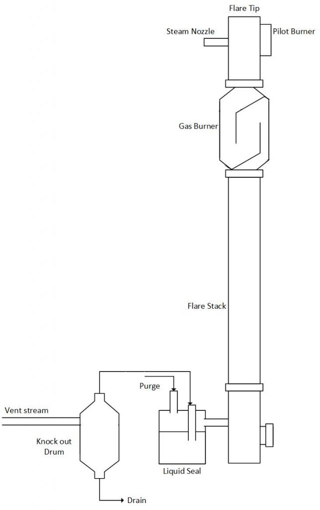
Parts of Steam Assisted Flare
The elements of an elevated steam-assisted flare generally consist of:
- Gas vent collection piping
- Utilities (fuel, steam, and air)
- Piping from the base up
- Knock-out drum
- Liquid seal
- Flare stack
- Gas seal
- Burner tip
- Pilot burners
- Steam jets
- Ignition system
- Controls.
Following diagram of a steam-assisted elevated smokeless flare system showing the usual components that are included.
Gas Transport Piping
Process vent streams are sent from the different release points of the plant to the flare location through the gas collection header. The piping is designed in such a way that minimizes the pressure drop. Valves in the flare header should be kept to an absolute minimum. The pipe layout is designed to avoid any potential dead legs and liquid traps. The piping is equipped for purging so that explosive mixtures do not occur in the flare system either on start-up or during operation.
Knock-out Drum
Liquids that may be in the vent stream gas or that may condense out in the collection header and transfer lines are removed by a knock-out drum. The knock-out drum is typically either a horizontal or vertical vessel located at or close to the base of the flare, or a vertical vessel located inside the base of the flare stack. The liquid in the vent stream can extinguish the flame or cause irregular combustion and smoking. In addition, flaring liquids can generate a spray of burning chemicals that could reach ground level and create a safety hazard. For a flare system designed to handle emergency process upsets this drum must be sized for worst-case conditions and is usually quite large. For a flare system devoted only to vent stream VOC control, the sizing of the drum is based primarily on vent gas flow rate with consideration given to liquid entrainment.
Liquid Seal
Process vent streams are usually passed through a liquid seal before going to the flare stack. The liquid seal can be downstream of the knockout drum or incorporated into the same vessel. This prevents possible flame flashbacks, caused when air is inadvertently introduced into the flare system and the flame front pulls down into the stack. The liquid seal also serves to maintain a positive pressure on the upstream system and acts as a mechanical damper on any explosive shock wave in the flare stack. Other devices, such as flame arresters and check valves, may sometimes replace a liquid seal or be used in conjunction with it. Purge gas also helps to prevent flashbacks in the flare stack caused by low vent gas flow.
Flare Stack
For safety reasons a stack is used to elevate the flare so that it does not present a hazard to surrounding personnel and facilities. Elevated flares can be self-supported, guyed, or structurally supported by a derrick. Self-supporting flares are generally used for lower flare tower heights (30-100 feet) but can be designed for up to 250 feet. Guy towers are designed for over 300 feet, while derrick towers are designed for above 200 feet. Free-standing flares provide ideal structural support. However, for very high units the costs increase rapidly. In addition, the foundation required and nature of the soil must be considered.
Burner Tip
The burner tip, or flare tip, is designed to give environmentally acceptable combustion of the vent gas over the flare system’s capacity range. The burner tips are normally proprietary in design. Consideration is given to flame stability, ignition reliability, and noise suppression. The maximum and minimum capacity of a flare to burn a flared gas with a stable flame is a function of tip design. Flame stability can be enhanced by flame holder retention devices incorporated in the flare tip inner circumference. Burner tips with modern flame holder designs can have a stable flame over a flare gas exit velocity range of 1 to 600 ft/sec. The actual maximum capacity of a flare tip is usually limited by the vent stream pressure available to overcome the system pressure drop.
Pilot Burners
EPA regulations require the presence of a continuous flame. Reliable ignition is obtained by continuous pilot burners designed for stability and positioned around the outer perimeter of the flare tip. The pilot burners are ignited by an ignition source system, which can be designed for either manual or automatic actuation. Automatic systems are generally activated by a flame detection device using either a thermocouple, an infra-red sensor, or, more rarely, (for ground flare applications) an ultra-violet sensor.
Steam Jets
A diffusion flame receives its combustion oxygen by diffusion of air into the flame from the surrounding atmosphere. The high volume of fuel flow in a flare may require more combustion air at a faster rate than simple gas diffusion can supply. High-velocity steam injection nozzles positioned around the outer perimeter of the flare tip, increase gas turbulence in the flame boundary zones, drawing in more combustion air and improving combustion efficiency. For the larger flares, steam can also be injected concentrically into the flare tip. The injection of steam into a flaring flame can produce other results in addition to air entrainment and turbulence.
Controls
Flare system control can be completely automated or completely manual. Components of a flare system that can be controlled automatically include the auxiliary gas, steam injection, and ignition system. Fuel gas consumption can be minimized by continuously measuring the vent gas flow rate and heat content (Btu/SCF) and automatically adjusting the amount of auxiliary fuel to maintain the required minimum of 300 Btu/SCF for steam-assisted flares. Steam consumption can likewise be minimized by controlling flow based on vent gas flow rate. The steam flow can also be controlled using visual smoke monitors. Automatic ignition panels sense the presence of a flame with either visual or thermal sensors and reignite the pilots when flameouts occur.