The vapor compression refrigeration cycle can be broken down into four different steps:
- Expansion
- Evaporation
- Compression
- Condensation
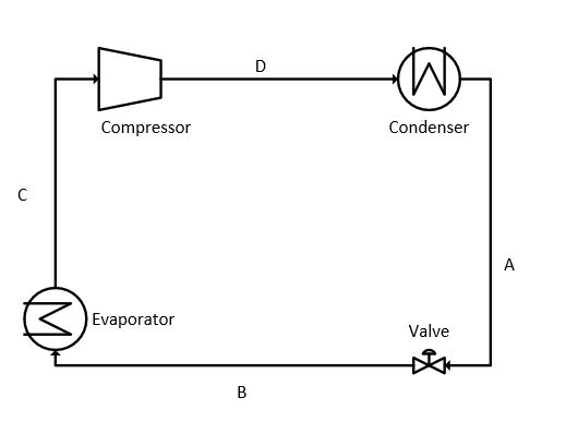
The process flow of the vapor-compression refrigeration cycle is represented in figure 1.
Read Also: Nitrogen rejection for natural gas using external refrigeration
1. Expansion
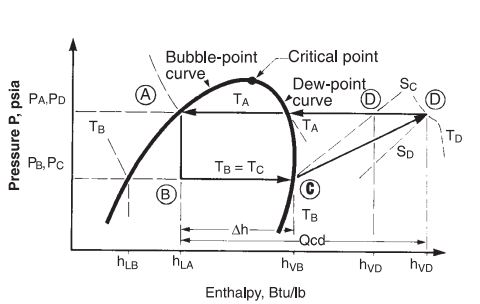
Expansion is the starting point in a refrigeration cycle. The starting point is represented as A in the PH diagram. The liquid refrigerant is available at this point. In the expansion step, the pressure and temperature are reduced by flashing the liquid through a control valve (CV) to the pressure at point B. The pressure at B depends on the type of refrigerant used in the process.
At point B the enthalpy of the saturated liquid and saturated vapors is represented by hLB and hVB respectively. The expansion through the valve is considered as isenthalpic because of no energy exchange during expansion. At point B, the two-phase mixture of refrigerant exists. The quality of the mixture at point B can be determined as:

2. Evaporation
The vapor formed in the expansion process does not have any effect on refrigeration. However, heat is absorbed from the process by the evaporation of the remaining liquid of the refrigerant. Evaporation is a constant temperature and constant pressure process. Generally, the evaporation takes place in a heat exchanger termed a chiller.
The refrigeration duty is the total amount of heat absorbed in the chiller by the process. The duty is generally expressed as tons of refrigeration or Btu/unit time. The refrigerant flow rate equation can be written as:

3. Compression
The saturated vapors of the refrigerant leave the chiller at a pressure and temperature equal to PC and TC. These vapors are compressed isentropically up to the pressure PA. The isentropic work for compressing the refrigerant can be written as:

h′VD is determined from refrigerant properties at PA and entropy of SC. Isentropic efficiency should be incorporated as refrigerant is not an ideal fluid and since the compressors for such services do not operate ideally. So, the actual work of compression can be calculated from:

4. Condensation
The vapors leaving from the compressor are superheated at the temperature of TD. These vapors cool down at nearly constant pressure to the dew point temperature (TA) of the refrigerant. During the de-superheating and condensation process, all heat and work added to the refrigerant during the steps of evaporation and compression must be removed so that the cycle can be completed by reaching Point A. Therefore, condenser duty can be expressed by adding the refrigeration duty to the heat of compression.

Condensation can be carried out using water, air, or another refrigerant. As the vapors are super-heated at the compressor discharge, the refrigerant condensing curve is not a straight line. It is a combination of desuperheating and constant temperature condensing.