Two-phase separators (Liquid/vapor separators) are one of the most common types of process equipment used in the industry. This article deals with the basic theory behind two-phase separators and the design of horizontal and vertical two-phase separators.
Working of Separator
There are three stages of separation in a separator. The first stage uses an inlet device to break the momentum of the incoming vapor/liquid mixture. This causes the largest droplets to impinge on the diverter and then drop by gravity. The secondary separation is the gravity separation of smaller droplets as the vapor flows through the disengagement area. The final stage is mist elimination where the smallest droplets coalesce so that larger droplets are formed which will fall down due to gravity.
Separator Types and Selection
Two-phase separators may be oriented either vertically or horizontally. In some cases, It is necessary to compare both designs to determine which one of these two is more economical. Separators can be designed with or without mist extractors. The vapor/liquid ratio is used to select the appropriate separator. Horizontal separators are preferred for low vapor/liquid ratio while verticals are suitable for high ratios.
Read More: Three-Phase Vertical Separator Design
Designing of Separator
The allowable velocity for the second separation section must be calculated to determine the disengagement area of the vessel. This can be done by applying the force balance on a settling liquid droplet. The gravity force acting on the droplet can be given by:

The upward drag force can be expressed as:

Heavier liquid droplets will settle at a constant terminal velocity. By equating both forces, the Ut can be expressed as:

As long as Uv < Ut, the liquid droplets will settle out. Typically, Uv is taken as 75% of Ut. Equation 3 can be written as:

While

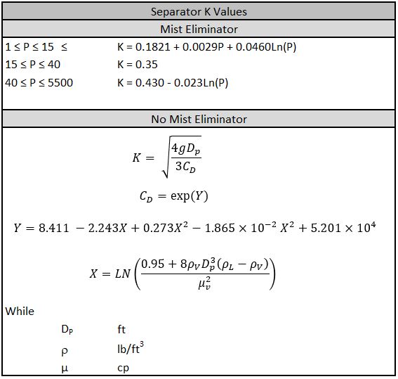
It is not practically possible to separate small droplets by gravity alone. These droplets coalesced together to form bigger droplets in the outlet device. These droplets are then settled by gravity. If there is no mist eliminator and the value of the droplet is known, then the K can be calculated from equation 5. The drag coefficient (Cd) can be calculated by curve fitting as shown in table 1.
Vertical Separator
For the vertical separators, the vapor disengagement area is the entire cross-sectional area of the vessel. The vapor disengagement diameter can be calculated from the following flow equation as given.


By rearranging equation 7

Typically, the calculated value is increased by six inches to accommodate the mist eliminator (if present). This value is taken as the required vessel diameter and the cross-sectional area is calculated using this diameter.
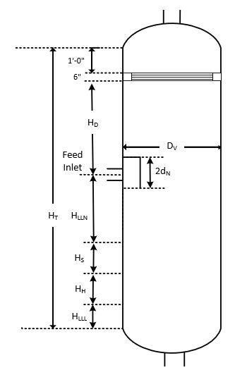
The total height of the separator is divided into multiple sections to determine the total separator height.
Watch: Heat Loss Model of Two-Phase Separator in Aspen HYSYS
Design Procedure of Vertical Separator
1. Vertical terminal velocity is calculated using equation 9.

Set conservative design value for Us as 0.75Ut.
2. Calculate the vapor volumetric flow rate as given:

3. Vessel diameter can be calculated with the volumetric flow rate.

3 to 6 inches need to be added in the diameter if the mist eliminator is present in the vessel. This increase will accommodate the support ring. The calculated diameter then rounded to the next 6 inches. If there is no mist eliminator then D=Dvd.
4. Calculate the volumetric flow rate of liquid using mass flow rate:

5. Select the holdup time from the table to calculate the holdup volume.
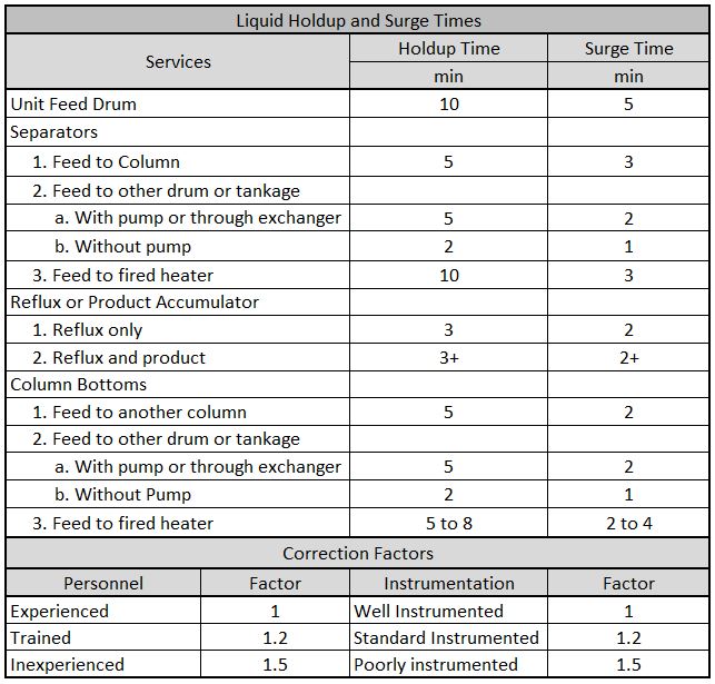

6. Calculate the surging volume by selecting the surge time from the table.

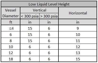
7. Select the low liquid level height from the table.
8. Calculate the height from the low liquid level to the normal liquid level.

If HH<1 ft then take the value of 1 ft.
9. Calculate the height from the normal liquid level to a high liquid level.

If HS<0.5 ft then take the value 0.5 ft.
10. Estimate the nozzle diameter using the equations below:


11. Calculate the height from the high liquid level to the centerline of the inlet nozzle.
With inlet diverter

Without inlet diverter

12. Calculate the disengagement height from the centerline of the inlet nozzle:

Use the minimum of equation 23 and equation 24 if no mist eliminator

Use the minimum of equation 23 and equation 25 if the mist eliminator is present

If there is a mist eliminator, allocate 6 inches to the mist eliminator and take 1 ft from the top of the mist eliminator to the top tangent line of the vessel.
13. Calculate the height of the vessel as

HME will be zero for no mist eliminator.
Horizontal Design Procedure
- Calculate the vapor volumetric flow rate, QV using the equation
- Calculate the liquid volumetric flow rate, QL, using the equation
- Calculate the vertical terminal velocity, UT, using the equation
- Select a holdup time from table 2 and calculate the holdup volume, VH using the equation
- If the surging volume is not specified, select surge time from table 2 and calculate the surging volume. Vs using the equation.
Obtain an estimate of L/D from the Table and initially calculate the diameter according to equation 27.

Round the value to the nearest 0.5 ft.
28. Calculate the cross-sectional area of the vessel.

29. Calculate low liquid level height, HLLL, using equation 29

Round the value to the nearest inch.
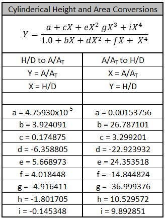
30. Using HLLL/D, obtain ALLL/A using the table and calculate the low liquid area.
If there is no most eliminator pad, the minimum height of the vapor disengagement area is larger than 0.2D or 1 ft.
If there is a most eliminator pad, the minimum height of the vapor disengagement area is larger than 0.2D or 2 ft. Hence, set Hv to a larger of 0.2D or 2ft. Using HV/D, obtain AV/AT using table 4, and calculate Av.
31. Calculate the minimum length to accommodate the liquid holdup and surge.

32. Calculate liquid dropout time

33. Calculate the actual vapor velocity

34. Calculate the minimum length required for vapor-liquid disengagement.

If L < Lmin then set L = Lmin.
If Lmin >> L, then increase HV and repeat the step.
If Lmin << L, then decrease the HV if it is greater than the minimum specified value.
Adjust the value of D to keep the L/D between 1.5 to 6.
2 Comments
Phase Separators – Chemiopedia · July 3, 2021 at 1:31 pm
[…] Read More: Two-Phase Separator Design […]
Three Phase Vertical Separator Design – Chemiopedia · August 12, 2021 at 9:56 am
[…] The nozzle diameter can be estimated using the method described in the Two-Phase Separator Design. […]
Comments are closed.