BARTON chart recorders are renowned for the accurate, reliable measurement and recording of pressure, differential pressure (DP), and temperature. Their fully mechanical operation is independent of external utilities that facilitate a low installation cost or portability.
The installed Barton charts have the ability to measure the temperature, pressure, and differential pressure simultaneously. The red pen indicates the differential pressure, the green pen indicates the temperature and the blue pen indicates the static pressure of the flowing stream. The internals of the Barton chart is given below:
1.1. Temperature Measurement and Calibration
Temperature is measured by a temperature bulb immersed in the flowing stream. The temperature value is transferred to the Spiral Barton Tube. The change in temperature alters the reading on the graph by a mechanical mechanism. The chart normally doesn’t require calibration but requires a check before startup. The chart is calibrated at 0, 25, 50, 75, and 100% of the full temperature range. The calibration includes the following steps:
- Remove the temperature bulb from the thermal well by loosening the packing nut and slipping it back on the bulb extension. Loosen the jam nut and remove the temperature bulb.
- Remove the thermal well from the socket
- Apply a temperature equal to 50% of the total temperature range.
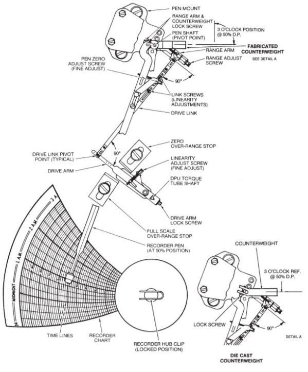
- Adjust the drive arm and the driven arm until they form an approximate 90° angle with the intermediate arm if the temperature on the graph doesn’t show the desired value
- Reduce the temperature to zero or the starting point of the temperature range. Fine-tune the zero adjustments with the zero-adjusting screw.
- Apply 100% temperature and set the pen to full scale by turning the adjusting screw.
- Reduce the temperature to zero or the starting point of the temperature range and check the zero reading.
- If zero adjustment is required, repeat steps 3 through 5 until the desired accuracy is achieved.
- Apply 50% temperature and observe the pen indication.
- If the pen indicates high or low, adjust the drive link to make a correction approximately 40 times the error — in the direction of the error.
- Reset the pen to the 50% line by slipping the pen at the range arm pivot point.
- Reduce the temperature to zero or the starting point of the temperature range and reset the zero point.
- If the zero offset is minor, reset the zero point with the zero and adjust the screw.
- If the zero offset is major, reset the zero point by loosening the bourdon mounting screws and rotating the connecting linkage to approximately zero. Fine-tune the zero adjustments with the zero adjust screw.
- Repeat steps 3 through 8 until the desired accuracy is maintained.
Read also: Flow Measurement
1.2. Pressure Measurement and Calibration
The static pressure of the flowing stream is measured by the Helical Barton Tube mounted within the chart. The pressure variation from the sensing element transfer to the Barton tube which transfers the change effect to the respective pen. The pen will draw the profile accordingly.
Differential pressure is measured by using the ballow. The resultant pressure of the upstream and downstream is transferred to the respective arm which draws the value on the chart.
- The static pressure and the differential pressure calibrate by the following steps:
- Adjust the range arm and drive arm at precisely the same distance from the back of the case.
- Place the drive link in the fourth hole from the pen shaft of the range arm.
- Adjust static pressure linkage to form 90° angles between the drive link and pivot points of the associated linkage, as follows:
- Apply 50% static pressure, center the thumb nut on the drive arm, and arrange the static linkage
- Set a 90° angle between the drive arm & link. Tighten the clamp block screw.
- Vary the length of the link to get a 90° angle between the range arm and the link.
- Slip the range arm on the pen shaft to 50% on the chart.
- Release pressure and reset the pen to zero indication, using the pen zero adjust screw for a fine adjustment (10% or less). For major adjustments (more than 10%), loosen the range arm lock screw and slip the pen to zero on the chart and retighten the lock screw.
- Apply 100% pressure and observe the pen. Make the necessary adjustments by turning the drive arm thumb nut counterclockwise if the pen is slightly underanged and clockwise if the pen is slightly over the range.
- Repeat zero and 100% adjustment until calibration at these two points is achieved.
- Apply 50% pressure and observe the pen indication.
- If the pen indicates high or low, adjust the drive link to make a correction approximately 40 times the error in the direction of the error.
- Reset the pen to the 50% line by slipping the pen shaft at the range arm pivot point.
- Repeat this step (7), as necessary.
- Release pressure and reset the pen to zero indication, using the pen zero adjust screw for precise adjustment.
- Repeat steps 4 through 8 until the calibration of zero, linearity, and span (0%, 50%, and 100% indication) is achieved.
- Assure range arm lock screws, thumb nut lock screws, and link screws are tight.
- Reconnect the DP linkage and range arm.
- Unlock the recorder hub clip and remove the temporary calibration chart.
- Replace the chart plate by sliding it into the chart plate retainer brackets and engaging each side into the chart plate latches.